Cold foil pinholes are small gaps in an intended metallic area. They can result from incomplete adhesive coverage, contamination, poor contact or loss of the transferred decoration. Start by locating when the gaps appear and whether their pattern repeats. The symptom alone does not prove that the anilox, UV system or foil roll is at fault.
This guide focuses on press-side diagnosis for label and packaging work. Anilox and UV checks below apply to the relevant flexographic system; sheet-fed offset jobs need checks matched to their own adhesive, blanket and transfer arrangement. The diagnostic sequence is a suggested investigation method, not a CFS test report or a universal press specification.
What causes cold foil pinholes?
Pinholing describes missing decoration, not a single failure mechanism. An incomplete adhesive image can leave gaps at transfer; contamination or uneven contact can interrupt an otherwise suitable setup. Decoration that initially transfers and later lifts needs a different investigation from a gap already present at the transfer station.
Check an affected sample under magnification, then compare samples from the earliest safe inspection point after transfer and after subsequent printing or finishing. Identify whether the spot exposes the substrate, contains a particle, or is a mark in an overprint rather than missing foil. A dark spot is not automatically a hole, and a gap in decoration does not by itself establish a hole through the packaging substrate.
For broader symptom identification, use the cold foil defects photo guide. Any illustrative image is a visual aid, not evidence of the root cause on your press.

Macro view of pinholes scattered across a gold cold foil monogram on black stock. Illustrative close-up — a visual aid for recognizing the symptom, not a photograph of a CFS factory test.
Read the defect pattern before adjusting the press
Pattern and timing narrow the investigation. Random spots, repeated gaps, bands and shadow images should not all trigger the same adjustment. Use the following table to select a check, then confirm it with the physical sample and process records.
| Observed symptom | Possibilities to investigate | Useful first check | What the observation does not prove |
|---|---|---|---|
| Random gaps visible immediately after transfer | Interrupted adhesive coverage, particles, wetting or local contact problems | Compare substrate cleanliness and the adhesive image with an approved run | That more adhesive is necessarily required |
| A similar gap repeats at a regular interval | A recurring disturbance associated with a rotating component or image repeat | Record the spacing and position; inspect the relevant components safely | That matching one circumference identifies the faulty component conclusively |
| Gaps or weak coverage form a band across the same part of the web or sheet | Nonuniform adhesive delivery, contact or material surface | Compare the affected zone with adjacent clean zones | That the entire foil batch is defective |
| Transfer looks complete initially but gaps appear after another operation | Adhesion loss, abrasion or a downstream compatibility problem | Compare samples before and after the operation | That the original defect was adhesive starvation |
| A faint duplicate image or metallic halo appears | Unwanted adhesive image, carryover, contact or web-handling disturbance | Locate the first station where the shadow is present | That low UV dose or static is the cause |
| Large patches are missing | A broader material, adhesive, contact or process-window problem | Compare the stock, materials and recorded setup with a known-good job | That the substrate alone is responsible |
Save an overview and a close-up with scale and machine direction marked. Use comparable lighting for subsequent photographs so a change in reflection is not mistaken for a change in coverage.
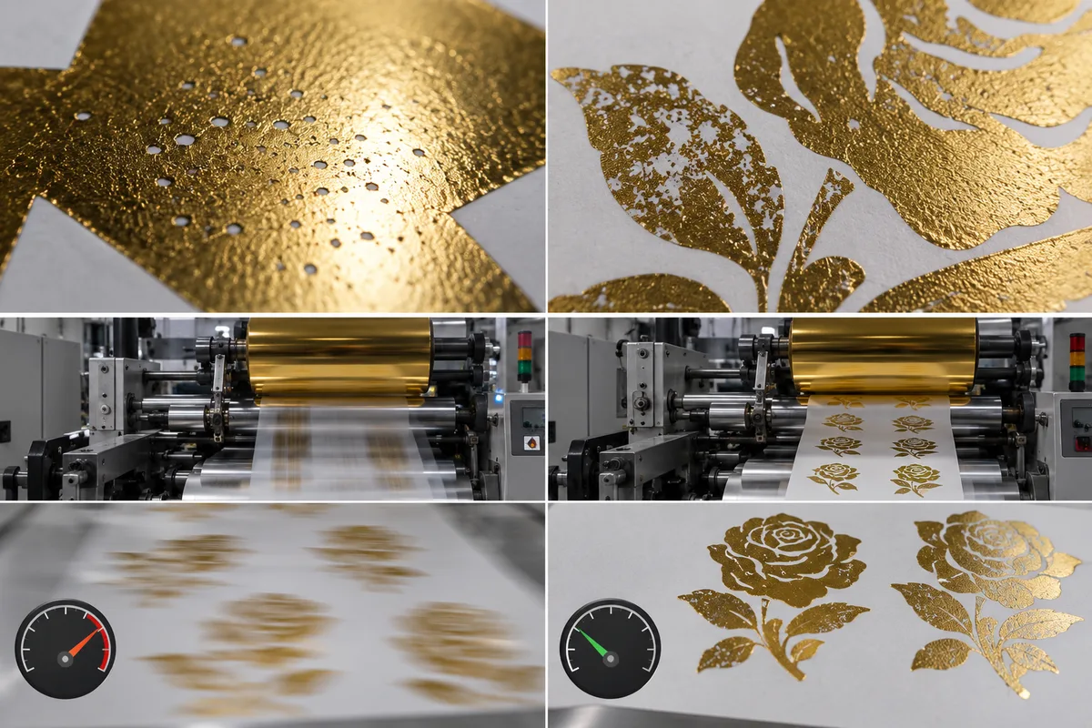
Defect patterns compared at different running conditions: pinholes, incomplete transfer, wrinkles and blurred overprint. Illustrative comparison — defect patterns on your press must be confirmed against physical samples.
Check the adhesive image and substrate first
A sound transfer needs the intended adhesive image and a compatible surface. Before changing material grades, compare both with the last approved setup for this job. Check the foil roll condition at the same time; there is no need to rule out every press variable before reporting suspicious incoming material.
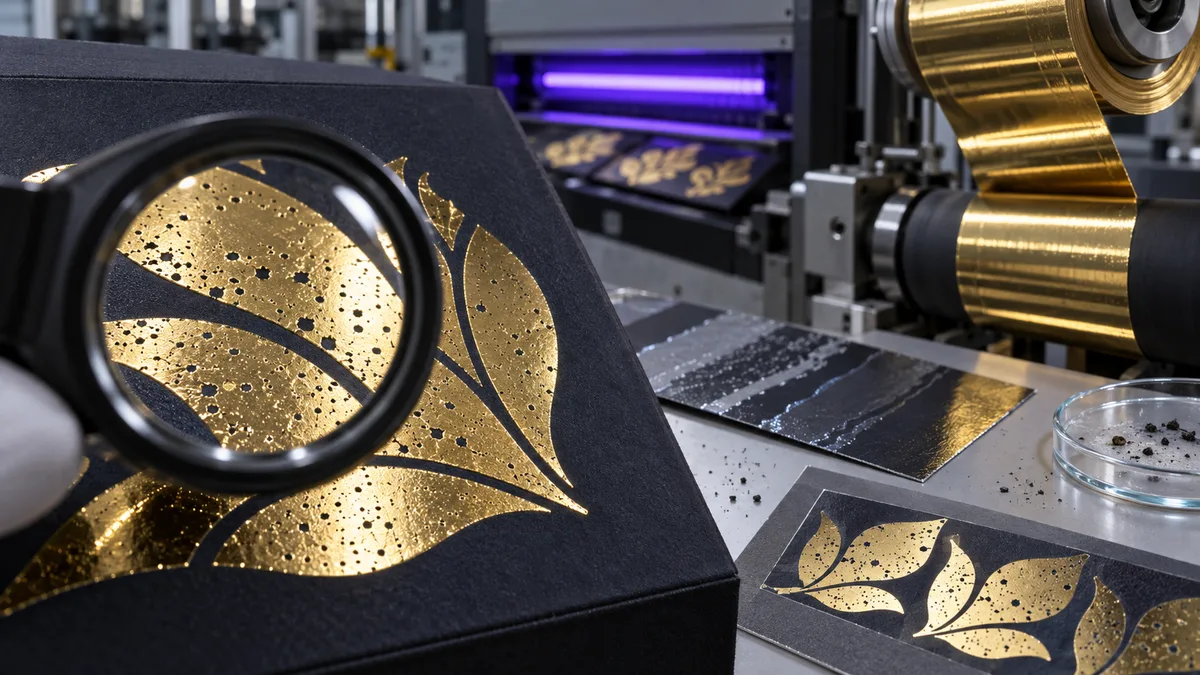
Press-side inspection of cold foil pinholes under magnification near the UV curing unit. Illustrative image — use your own retained samples and process records for diagnosis.
—Inspect contamination and surface condition
Look for particles, coating variation and a change of stock or lot. Check the web-cleaning and static-control equipment using the manufacturer's maintenance procedure. Meech's label-converting guidance explains that static can attract dirt and dust to a moving web, affecting print quality. That makes contamination worth checking, but it does not establish static as the cause of every random gap.
Compare suspect stock with retained approved stock when a controlled comparison is practical. If evaluating surface treatment, use the substrate and adhesive suppliers' specified method and acceptance criteria. Do not use a generic dyne target as a guarantee of foil adhesion.
—Inspect adhesive delivery on the actual printing system
On a flexographic line, inspect the plate, metering arrangement and anilox condition. Harper's anilox-management guidance distinguishes plugged cells from wear and recommends before-and-after cleaning inspection. Recoverable cell volume and permanent damage require different actions. A nominal engraving specification does not tell you the roll's current condition.
Use cleaning methods approved for the roll and adhesive chemistry. Do not compensate for contamination by immediately selecting a higher-volume anilox. First establish whether the existing equipment is delivering the intended, consistent film.
For sheet-fed offset, evaluate the adhesive image and blanket/transfer setup specified for that machine. Eagle Systems' adhesive-setting guidance describes finding a usable window between pinholing at one end and other defects at the other, with settings dependent on stock and blankets. Its example is not a flexo BCM prescription. The useful principle is to establish and record a job-specific working window rather than keep increasing adhesive.
—Check contact and material matching
Inspect the permitted nip, alignment, foil path and tension settings against the approved setup. More pressure is not a universal correction. Clean coverage and acceptable fine detail must both survive any adjustment.
KURZ's web-fed cold-transfer FAQ emphasizes matching the adhesive, substrate and transfer material. For difficult paper surfaces, the uncoated-paper guide provides a separate planning reference; do not simply accept pinholes as unavoidable or promise that one primer will fix every stock.
What if pinholes improve when you slow down?
Improvement at a lower speed shows that the changed running condition matters. It does not isolate the cause. Speed can change the available curing exposure, adhesive-transfer behavior and mechanical stability, so a successful slow run is a diagnostic observation rather than proof of adhesive starvation.
For a UV system, compare measured output and the actual exposure arrangement with the adhesive supplier's requirements. Record the instrument, spectral band, measurement position and running condition. EIT's radiometer guidance distinguishes energy density from peak irradiance; lamp power percentage alone is not the same measurement. UV readings should be assessed alongside the specified cure and adhesion checks, not treated as proof of cure by themselves.
Do not transfer a dose from another adhesive, instrument band or machine into this job. Likewise, do not apply a UV-flexo remedy automatically to sheet-fed offset: KURZ's sheet-fed FAQ describes its distinct adhesive-image and blanket/impression-cylinder transfer arrangement.
After a controlled adjustment, verify the result at the intended production condition. If acceptable transfer and finished-product performance cannot be maintained there, obtain supplier guidance before releasing the job.
Follow a separate branch for ghosting and edge breakup
Ghosting is a shadow or unintended secondary image; edge breakup is loss of definition around the intended image. They may appear alongside pinholes, but neither should be treated automatically as another sign of insufficient adhesive.
Find the earliest safe inspection point where the unwanted pattern is visible. If it is already associated with the printed adhesive image, investigate image formation and contamination. If it appears at transfer, inspect the approved contact, foil handling and release conditions. If it appears only after overprint or handling, focus on that operation rather than continuing to adjust the foil station.
Record any regular spacing and whether the shadow follows the artwork. These are clues to test against the machine layout, not a guaranteed component diagnosis. For broken fine edges, compare edge definition as well as solid coverage after each change. An adjustment that fills the solid but closes small text is not a successful correction.
Where decoration is lifting after transfer, use the cold foil adhesion test method for labels to organize the agreed checks. Match the method and acceptance criteria to the finished application.
Re-test with one documented change at a time
A useful re-test separates the suspected cause from other changes and checks the finished result. The procedure below is a proposed recordkeeping method, not a published test standard or a claim of measured CFS improvement.
- 1Retain the baseline. Label an affected sample and the last approved sample, with the job, stock, foil and adhesive identifiers.
- 2Choose one hypothesis. State the observation and the next check, such as suspected contamination or a difference in measured adhesive delivery.
- 3Make one controlled change. Stay within approved limits. If a component change necessarily changes several properties, record those differences rather than claiming that only one property was tested.
- 4Compare the same artwork area. Use consistent lighting, magnification and inspection conditions. Record both improved and newly introduced defects.
- 5Verify at production conditions. Check startup and stable running as relevant, and repeat the agreed finished-product checks after the applicable conditioning period.
- 6Approve and document. Release production only against the customer's quality criteria and the converter's control procedure. Keep the accepted sample and settings together.
Stop and isolate equipment under the site's safety procedure before hands-on cleaning or inspection. Never reach into a moving nip or bypass guards to observe a defect. Changes involving UV equipment, chemicals or treatment systems belong with trained personnel following the relevant instructions.
Suggested trial record. The fields below are deliberately blank. They are not example measurements or pass limits.
| Record field | Entry for this trial |
|---|---|
| Job, artwork revision and sample ID | __________ |
| Process, press and inspection stage | __________ |
| Substrate grade, lot and surface information | __________ |
| Foil grade/roll and adhesive grade/lot | __________ |
| Relevant anilox, plate or blanket identification | __________ |
| Speed, contact/tension settings and applicable cure measurements | __________ |
| Defect pattern and baseline observation | __________ |
| Hypothesis, change and other affected variables | __________ |
| Result at production condition and after finishing | __________ |
| Acceptance criteria, decision, operator and date | __________ |
The press setup checklist can support the next job's baseline. Do not turn one successful trial into a universal setting for a different stock or adhesive.
What to send when asking for technical support
Send enough information to locate the failure stage, not just a close-up of a metallic surface. Include an overview, a scaled close-up, the machine direction, affected and approved samples where available, and the material identifiers and trial record above. State whether the problem began after a material change, maintenance, speed change or downstream operation.
If a foil roll appears damaged or the defect follows a particular material lot, retain that identification and involve the supplier early. Avoid consuming the entire suspect roll while making unrelated adjustments.
Discuss your cold foil defect with CFS. For evaluation of an alternative material, request a cold foil trial sample with the intended substrate and press details. A clean sample from a different setup does not replace validation on your production line.
Frequently asked questions
Can the foil itself cause pinholes? +
It can be part of the investigation. Compare the suspect roll with an approved roll of the same suitable grade under documented conditions, and inspect retained incoming material. An improvement after a roll change is evidence to investigate, not proof by itself: rethreading and other setup changes may also affect the result.
Are small pinholes acceptable if adhesion passes? +
Passing adhesion does not automatically satisfy appearance requirements. Agree the permitted defect size, frequency, location and viewing conditions with the customer for the actual job. Do not invent a universal pinhole tolerance or use a pass on one test to waive a different requirement.
Does holographic cold foil need a different diagnosis? +
Use the same pattern-and-stage investigation, while checking the specific grade's release and processing requirements. The word "holographic" alone does not establish a thicker carrier, greater pinhole risk or a different UV target. Obtain the proposed grade's technical information rather than applying those assumptions.